 The Tiny84 paper car controller includes the following two features by default. First there is a motor speed controller which allows you to directly drive two low current motors. Using FET transistors attached to the Tiny84 I can drive two high current outputs. Typically the Tiny84 delivers 20mA of current while the FETs extend this to allow 500mA per motor. To wire up a motor you need to wire one of the motor leads to the M1 or M2 pad on the board. The other motor wire is connected to the Vcc pad. When the FET is turned on with a logic ‘1’ on its gate input, current will flow through the motor.
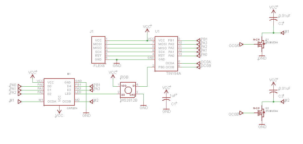
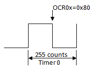
The motor speed control uses hardware timer 0. The Arduino developers have already used Timer 0 for the millis() function so I built on top of their design rather than changing it. The Arduino is automatically setup to use Timer 0 as a fast PWM running at 8MHz/64/256 = 244kHz. Timer 0 acts a a counter that counts from 0 to 255 and then wraps back to 0. I setup two hardware compare registers OC0A and OC0B to drive the motor FET transistors. Using the output compare register I can write an 8 bit value which tells the hardware when to toggle the output on the compare pin. This means that by just setting the OCR0x registers I can set the on/off time that drives the motor. This provides independant speed control for both motor and requires vitually no processor overhead. The following diagram shows the 50% duty cycle waveform that would be output on the output compare pin when the OCR0x register is set to 0x80 128 decimal. The following code sets up the hardware PWMs
//Set motor FET pins to output
pinMode(M1,OUTPUT);
pinMode(M2,OUTPUT);
//Setup hardware PWM
TCCR0A |= 1<
Controlling motor Noise
While testing the paper car 2014 design I noticed that I would get brownouts when the motors were switched on and off. A quick look at the voltage rails showed that the supply was drooping ~1V when the motors started up. The instantaneous current consumption of each pager motor is ~350mA which was enough to cause the current in the battery leads to droop due to resistance. While the voltage drop was not enough to reset the processor it was enough to reset the WS2812B LED resulting in annoying flickering. My first attempt to reduce the motor noise was to PWM the motor to reduce the inrush currents but narrow voltage spikes were still causing problems so I needed to filter them out.
I added 0.01uF decoupling capacitors directly across the motor leads. These capacitors act as a dead short to high frequency noise while at the lower PWM frequency they appear as open circuits. The effect of the capacitor is to filter out any high frequency motor commutation noise spikes which had previously caused problem for the LEDs.
WS2812B operation
The second default feature is the inclusion of a WS2812B LEDs and software driver. The code for this is included in the paper car library. To include the WS2812 library code you need to add the following two lines of code to the start of your sketch.
#include
PaperCar2014 LED(10); //define 10 LEDs in string
Two functions are included to allow you to control the on board LED and a string of WS2812B LEDs attached to the LED pad. The first instruction allows you to configure the colour for each of the LEDs in the string. LED zero is the onboard LED while additional LEDs are numbered one, two etc the further out they are located in the LED string. To set a LED colour you use the function :
LED.setColorRGB(LED,red,green,blue);
Setting the LED colours does not have an immediate effect on the LED colours, instead colour changes occur when you issue a render command. This allows you to synchronously update all of the LED colours at one time. The render command is as follows:
LED.WS2812_render();
The board mounted LED can also be controlled by the following macro definitions. LED_red(),LED_green(),LED_blue(),LED_yellow(),LED_cyan(),LED_magenta(),LED_white(). These macros immediately write the set the colour and then render it to the LED.
Technical details
The LED driver is coded in assembler and is designed to bit bang the LED data to the WS2812B. The timing is critical so interrupts are disabled while the LED data is sent out to the LED chain. Disabling interrupts will create complex timing interactions that are difficult to predict. Interrupts are disabled for approximately 24*400kHz*number of LEDs; that is the time it takes to shift out the 24bit led pattern to each LED in the string. If you use interrupts or have critical timing you will need to deal with this, however most users won’t notice this effect at all.
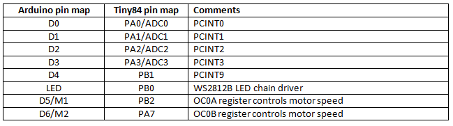
Wiring Reference