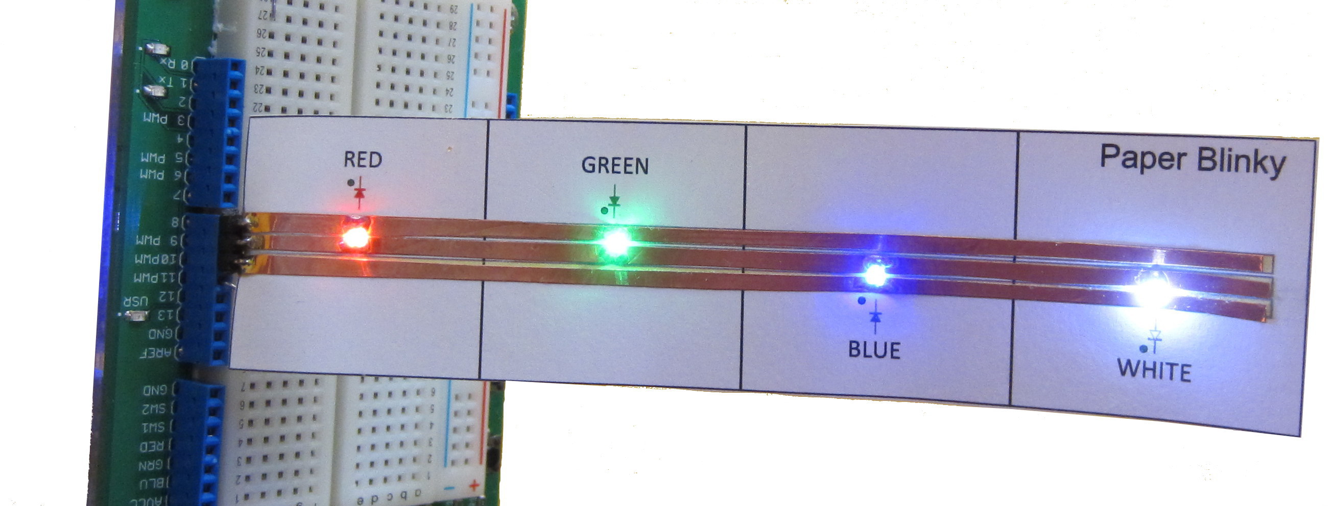
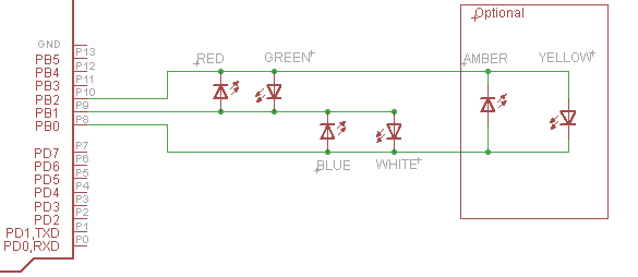
 Paper Blinky is a simple four LED circuit that allows you to develop Arduino code to turn the LEDs on and off in a variety of patterns. Rather than wiring the LEDs on a proto-board they are assembled on a permanent paper circuit; this allows you to rapidly plug in the circuit to demonstrate your project code. The attached schematic shows how the four LEDs are wired and shows how you could extend the circuit to drive six LEDs. Paper Blinky provides a robust circuit that is easy to assemble and is fully reusable. To simplify the circuit assembly the current limiting resistors have been omitted and instead I rely on the AVRs limited 40mA drive capability to keep the LEDs from burning out. Furthermore the LEDs are wired so that they are actually pulsed on and off very rapidly if you want to light all of the LEDs at once. The LEDs are said to be Charlieplexed, where the LEDs are pulse width modulated which limits the average current because the LEDs are not on all of the time.
Charlieplexing allows you to drive more LEDs with fewer pins. In fact Charlieplexing allows you to drive N*(N-1) LEDs with only N pins. In this example three pins allows us to drive up to 3*(3-1) = 6 LEDs. To turn on a LED the anode is driven high while the cathode is driven low.
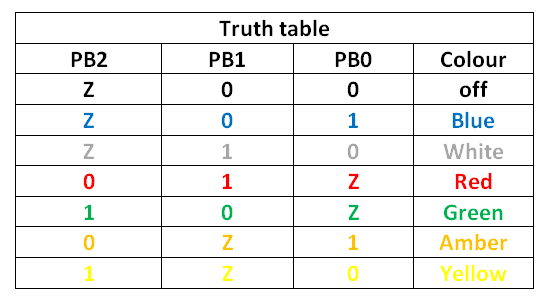
 From the schematic I created a truth table that shows the useful states for the three pins. Most of the pin drive combinations have no impact and the LEDs are off. Only seven of the truth table states are of interest as they turn on/off each of the six LEDs. Notice that I have Charlieplexed the pins so that one pair of pins drives each LED; unused pins are tri-stated (Z state) by setting the Arduino pin to an input. When a pin is tri-stated it is not actually driven and the level on the pin is unknown and could be high or low. When a pin is tri-stated it is left floating and is electrically disconnected from the rest of the circuit. To tri-state an Arduino pin you need to set the data direction register (DDR) bits to zero to create an input (inputs are not driven) and then you need to set the PORT pin to zero so that the internal pullup is turned off.
Arduino Example code
The processor of the Arduino is an AVR chip that has internal registers to define the operation of its I/O ports. Two of the I/O registers are used in this Blinky example. The data direction register (DDRx) is used to define the direction of the port bits which can either be an input or an output. Outputs drive the pin while inputs listen to the state of the pin. Inputs expect that some other device connected to the pin will drive it. To set a bit as an output a one is written to the bit position within the DDRx register, zeroes define inputs. The line of code (1<<5) tells the compiler to shift a "1" into bit position 5. Using this convention along with the "|" (logical OR) I can assemble a bit pattern that will set specific pins as outputs. The second register that is used is the PORTx register which actually drives the pin output high or low. Note that the I/O pin is only driven if the DDRx bit is also set to a "1" while the PORT bit is toggled. The Arduino sketch shows how to drive two of the LEDs. You should try to extend the program so that it lights the remaining two LEDs as well. Notice that I set the data direction register (DDR) first and then I set the PORT pins. I do this to avoid false flashes on the pins. // Paper Blinky Example 1 // Plug the Paper Blinky into Arduino pins 8,9 and 10 (PB0,PB1,PB2) #define ms_delay 1000 void setup() {} void loop() { DDRB = (1<<1 | 1<<0); //PB0 and PB1 set to output PB2 is an input PORTB = (1<<0); //Blue PB0 = 1 while PB1 = 0, PB2 = 0 delay(1000); DDRB = (1<<1 | 1<<0); //PB0 and PB1 set to output PB2 is an input PORTB = (1<<1); //White PB0 = 0 while PB1 = 1, PB2 = 0 delay(1000); } Note that you can't drive all of the LEDs on at the same time but you can create the illusion of this by cycling through each of the LEDs flashing them very quickly. If the delay between the code that turns on a LED is commented out, each LED will flash briefly, one after the other. The sequence of flashes is so fast that our eyes detect the LEDs as being fully on. This persistence of vision is what allows us to see continuous images on a TV. The rate at which you flash the LEDs must be fast enough to trick our eyes into believing the LEDs are fully on. The minimum rate is ~25 to 30 flashes per second. If you flash the LED 30 times per second then the frequency is 30Hertz and the pulse width is 33 milliseconds. Try adding a small delay between LED pulses to see when the flashing becomes visible.