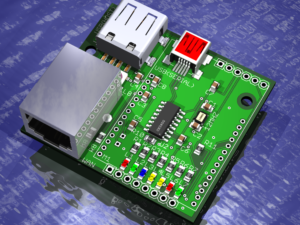
 As I continue to develop embedded Linux designs I needed a smaller design that can be deployed as a standalone project. The new design consists of a small 4x5cm PCB that acts as a carrier for the HLK_RM04 wifi module. I needed this PCB to provide a USB to serial port for debugging as well as an RJ45 Ethernet port and a USB-A host connector along with some LEDs. This board when equipped with an HLK_RM04 module forms a complete embedded Linux computer.
This embedded Linux computer is not a Raspberry Pi or Beagle Bone Black competitor. The HLK-RM04 has no video output and provides limited processing (380MHz) and 32M memory. What the HLK-RM04 does provide is a very inexpensive $10-15 Linux computer that can be easily embedded in a project. With WiFi, USB and Ethernet it forms a great robotics platform or a remote telemetry and data logging devices. I am thinking of using it as an Internet radio and adding features to directly drive WS2812B RGB LED strips.
For the last few months I have been building a development environment for this board and module. The development environment runs on Ubuntu and provides complete control of the software builds. Linux on an embedded computer is divided into two components; the Uboot loader and the kernel. I have infact created two build tool chains for each of these components. I can build and test new Uboot loaders or I can modify the Linux kernel as required. The Linux kernel is built using the OpenWRT build environment.
The schematic for version 2 of the breakout board is located here. 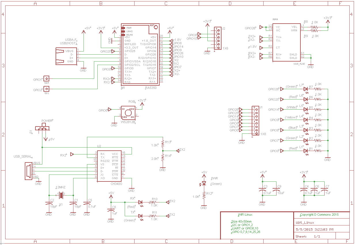
I have provided a pin map for all of the GPIO available on this board. Note that some of the alternate functions are mutually exclusive so if you enable UARTF or I2C you are giving up the GPIO pins for those ports. As I proceed with my development of this board I am hoping to illustrate how each of these functions can be used to create your own custom application.
I should explain the rational for the breakout board design. The HLK-RM04 comes with 2mm header pins which are not very standard in North America, so at a minimum I wanted to break out the GPIO pins to 0.1” centers. I included a single RJ45 port initially so that I could TFTP load new images to the HLK module. The version of Uboot I installed only includes wired Ethernet support so I couldn’t do this wirelessly for now. I hope that in time I will be able to remove the RJ45 connector by upgrading Uboot to support wireless TFTP or serial Kermit. The USB-A host port is a huge asset because it allows me to install Flash memory sticks, which are directly readable from the Linux OS. This feature is extremely useful for data logging. The USB host also accepts USB to serial dongles, USB cameras and pretty much anything else you might want to plug into a Linux computer. For control of the module the Uartlite interface is wired to a CH340 USB to serial converter. This allows me to configure the module even if I have no network connectivity. This is absolutely essential from a developer’s point of view. Once your network is configured you can then remotely access the module using the SSH secure shell from anywhere in the world.
I would be remiss not to mention a few of the web sites that helped me to get to this point. I started with the HLK-RM04 Openwrt web page. This was helpful but not all that clear and there were a number of documentation inconsistencies. http://wiki.openwrt.org/toh/hilink/hlk-rm04 The Australian site for the Carambola has lots of useful tips but it would appear they have moved on to supporting the Carambola2 which uses a different chipset. There are not a lot of new posts about the Carambola but what they have is very useful. http://www.8devices.com/wiki/carambola:1:demo_projects
The final nod goes to Vocore, which is current and has lots of detailed information. www.vogner.cn I have purchased a few modules and they are great; still I prefer 0.1” centers.
I buy my modules directly from HiLink http://www.hlktech.net/product_detail.php?ProId=49 Pay extra for the 32M module, its worth it. Tell them I sent you. My goal is to provide a more fully documented design based specifically on the HLK-RM04 and Ralink RT5350 system on a chip.
Over the next few months I will be publishing all of the details for configuring and controlling the module. The specifics will include details on the following:
Step 1 Install Uboot over factory default
Step 2 Ubuntu_12_Install
Step 3 Build Uboot
Step 4 Install_Openwrt
Step 5 Build_Openwrt
Step 6 Compile_User_Program
Step 7 Fast_GPIO_in_C
Step 8 USB
Step 9 Writing a kernel driver
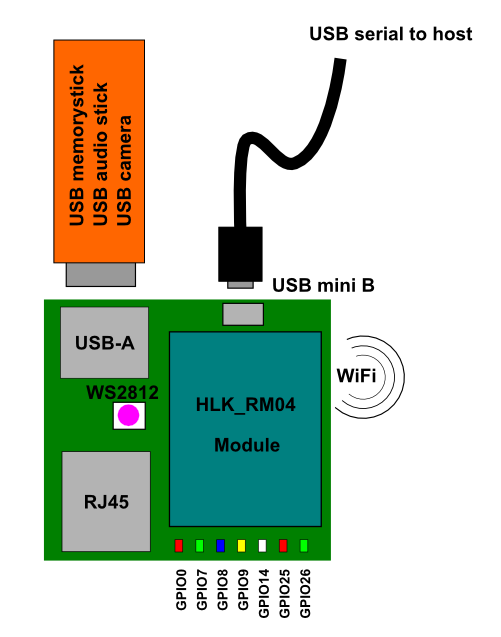
So let’s get started by describing what it is that I have built for this project. My initial design of the support board has been tested and I am preparing to build version 2 of the board to address a few of the errata that I found. To put things into perspective I think a block diagram of the system is in order. The green PCB breaks out the 2mm module connectors to 0.1″ solder tabs and provides the connectors for one Ethernet port and one USB host port. To provide a configuration port a USB to serial CDC interface has been added. The USB mini B port also doubles as the power source for the whole assembly.
GPIO
Each of the GPIO pins has been equipped with an LED so that you can easily observe when the GPIO bit is toggled. I have also routed one of the GPIO to a WS2812B RGB LED so that I can provide some more interesting visual feedback from the board.
Features
360MHzMips processor Ralink RA5350 system on a chip
8Mbyte flash/ 32Mbyte SDRAM
802.3 wired ethernet port RJ45
802.11 wifi
USB-A host port
LEDs on all I/O
8 GPIO, UARTF (Rx,Tx)
I2C (SDA, SCL)
CH340 USB to serial converter
GPIO pins
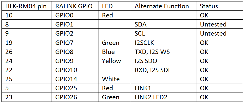
The following table is a modified version of the HLK-RM04 pin functions that are located on the Openwrt site. It corrects the USB polarity and properly names GPIO1, 2 as I2C pins. I have also removed the references to netgape, which is likely a translation of port, but for me it was confusing so I removed it.
LED Definition
LED1 –> power LED
LED2 –> EPY_LED4_N
LED3 –> WLAN_LED_N
Pin Definition
No.     Function        RT5350 Pin      Dir     Explanation
1       VDD5V           -               I       Power input
2 	GND 		GND 			GND
3 	WLAN_LED 	WLAN_LED_N 	O 	WIFI LED
4 	3.3V 		-		O 	3.3V power output <300mA
5 	LINK1 	        EPHY_LED3_N 	I/O 	LAN LED1/ GPIO25
6 	USB_M		UPHY0_PADM	D- 	USB signal D-
7 	USB_P		UPHY0_PADP	D+ 	USB signal D+
8 	SDA		I2C_SD 		I/O 	SDA/GPIO1
9 	SCL		I2C_SCLK 	I/O 	SCL/GPIO2
10 	GPIO0 	        GPIO0 		I/O 	GPIO0
11 	TXOP1 	        EPHY_TXP_P3 	I/O 	LAN 1 TXP, Pin 1
12 	TXON1 	        EPHY_TXN_P3 	I/O 	LAN 1 TXN, Pin 2
13 	RXIP2 	        EPHY_RXP_P4 	I/O 	WAN RXP, Pin 3
14 	RXIN2 	        EPHY_RXN_P4 	I/O 	WAN RXN, Pin 6
15 	RXIN1 	        EPHY_RXN_P3 	I/O 	LAN 1 RXN, Pin 6
16 	RXIP1 	        EPHY_RXP_P3 	I/O 	LAN 1 RXP, Pin 3
17 	TXON2 	        EPHY_TXN_P4 	I/O 	WAN TXN, Pin 2
18 	TXOP2 	        EPHY_TXP_P4 	I/O 	WAN TXP, Pin 1
19 	RTS_N 	        RTS_N 		I/O 	RTS/I2SCLK/GPIO7
20 	UART_RX 	RXD2 		I 	Uartlite RX2/GPIO16
21 	UART_TX 	TXD2 		O 	UartliteTX2/GPIO15
22 	RXD 		RXD 		I/O 	RX/I2SSDI/GPIO10
23 	LINK2 	        EPHY_LED4_N 	I/O 	WAN LED2/GPIO26
24 	CTS_N 	        CTS_N 		I/O 	CTS/I2SSDO/GPIO9
25 	RIN 		RIN 		I/O 	RING/PCMDTX/GPIO14
26 	TXD 		TXD 		I/O 	TX/I2SWS/GPIO8
27 	1.8V 		- 		O	1.8V output <300mA
28 	VDD5V 	        - 		I	5V input
Resources
1 I2S (muxed with UARTF)
1 PCM (muxed with UARTF, data only) - PCM clock, sync, and RX pin are not wired,
  but PCMDTX is available and useful for timing-sensitive 1-wire serial protocols
  at 19.531kHz~20MHz
12 GPIOs (some features reserve GPIO: I2C[2], UART[2], UARTF[5], EPHY_LED[2], GPIO0[1]
  and can be disabled for more GPIO).