 Like many developers I purchased an HLK-RM04 WiFi route module with the intent of Flashing my own Linux image onto it. So I wired it up and tried to build an OpenWRT image using a virtual machine running Ubuntu. What I ended up with is a bricked module and I had no tools to re-flash the SPI so that I could recover. Undaunted I decided to build a test bed that would allow me to develop module code without the risk of bricking the module because of bad code.
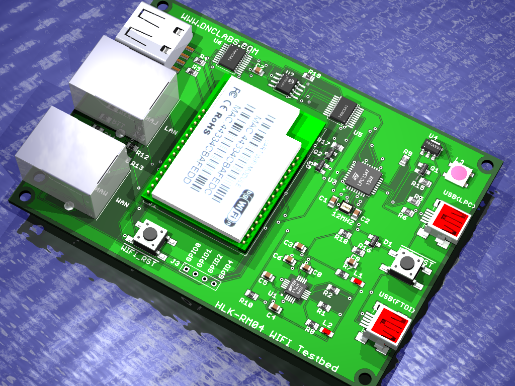
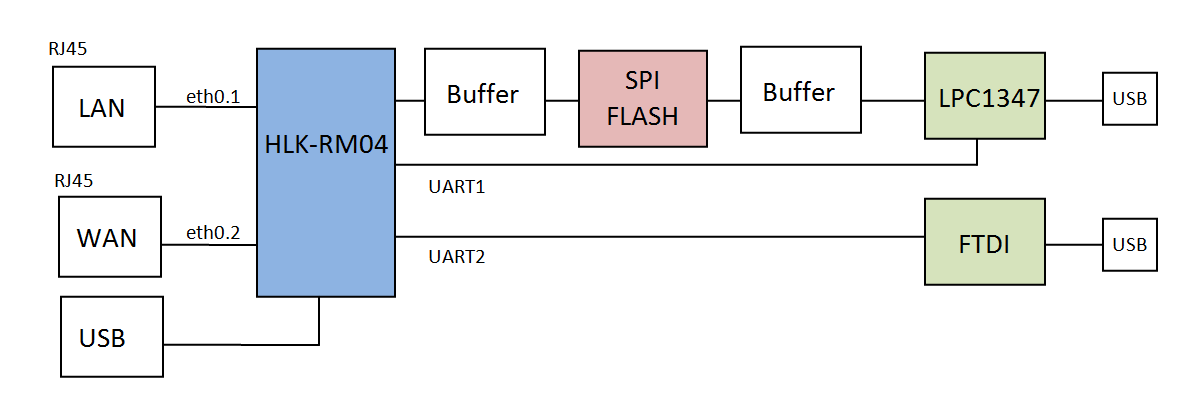
The test bed I designed provides access to all of the modules features including the LAN, WAN ports as well as the two serial ports and GPIOs. To allow me to restore the SPI FLASH code on the module I actually remove the FLASH memory from the module and mount it on my test bed. Using buffers I can allow the module to access the SPI memory or I can access it from an LPC1347 mounted on the test bed. The LPC2347 has been programmed to run FlashROM on it so that I can read/write and erase the SPI FLASH which allows me to restore the module no matter what code is loaded into the FLASH.
The block diagram of the test bed is shown here. The SPI Flash is removed from the module and soldered to the test bed. Six wires are used to connect the module to the test bed mounted SPI Flash memory. To connect to the module I left a hole in the test bed PCB so that I can access the SPI Flash pads on the under side of the module. This allows me to easily solder the module in place.
Once I had assembled the module test bed I tested it. First I wanted to reset the KLK-RM04 module to its factory defaults using the serial port configuration tool as described below. Then I tested that the module actually worked; that is the HLK-RM04 boots up as a router with the SPI memory mounted on the test bed. Finally with a know working module I created a copy of the SPI Flash so that I have a complete copy of the original factory fresh image. With the original image I can now always restore the module to its original state. In other words, I can de-brick the module. With this reassurance I proceeded to re-flash the boot loader on the module so that I can use TFTP to load new Linux images. The original H-Link boot loader is not suitable for downloading Linux images so I replace the boot loader with Uboot.
Testing and backup
The following steps provide details of how I tested the module. In particular I wanted to make sure that the test bed with the SPI Flash mounted on it would work as expected. Once the test bed and module are up and running I could then save a copy of the original factory firmware. The following procedure is only executed once when I first set up the module on the test bed. The three steps are as follows and each of the subsequent sections details how to perform the tests.
- Solder the SPI Flash to the test bed.
- Reset the HLK-RM04 to its factory defaults.
- Test the serial, WIFI and LAN/WAN ports using the default firmware to ensure that nothing was damaged when I soldered the SPI FLASH to the test bed.
- Backup the original SPI Flash image for disaster recovery.
The first thing we need to do is remove the SPI Flash from the HLK-RM04 module. Using a hot air pencil I removed the SPI Flash from the bottom of the module. I then soldered the SPI flash to the test bed. Next I plug the module into the test bed. There are two rows of SPI connections on the test bed that allow me to solder 6 short 30AWG wire from the test bed to the pads of the HLK-RM04.
We also need to install the LPC1347 firmware onto the test bed. The binary code is located here FlashRom.hex. To load this code into the LPC1347 plug in the USB cable connected to the LPC. Press and hold the reset button for three seconds then release the reset. Your host computer should see a flash memory device enumerate. Find the USB memory device and erase the current firmware. Then copy the binary file from above onto the USB device. Finally briefly press the reset button and your new LPC1347 firmware will start running.
Now we can start testing.
Configuring HLK Module using serial port
This step restores the HLK-RM04 to its default settings. This only works if you have the original firmware installed on the module.
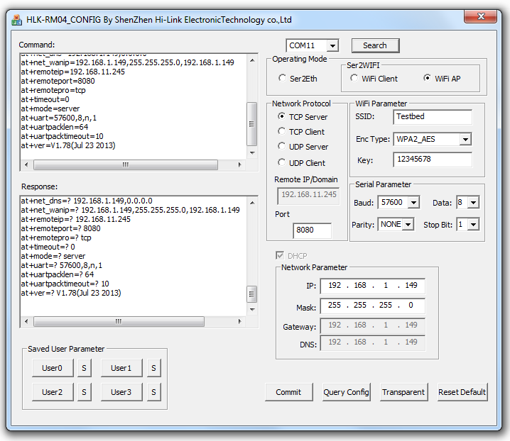
Using the HLK-RM04_CONFIG_english.exe file that is provided by Hi-Link it is possible to reconfigure the module. The test bed is designed to provide USB to serial access using an FTDI chip so that you can re-program the default setting for the module. To start the serial configuration code you need to.
- Power up the module and wait ~30sec.
- Press the WIFI_RST button ~6sec on the test bed which will cause the module to enter the factory default setting.
- Connect a USB terminal to the USB(FTDI) port and set the baud rate to 57600
- Start HLK-RM04_CONFIG_english.exe and query the device settings. Both the red and green test bed LEDs should flash as the data is transferred.
- Press “Query Config” and make sure that the host application can communicate with the module. Then press “Reset Default” so that the system is restored to its default settings. I do this so that the remaining instructions are always the same.
- Press the LPC_RST button to restart the system when you have finished configuring the module using the serial port.
Getting HLK-RM04 Running on Windows
In this step we test the module set up by using it as a wireless serial device. Serial messages are received from the host PC using PUTTY which is an internet terminal application.
The first step are to power the module and wait for the system to initialize ~30-60seconds
- Add the WIFI MAC address of your module to your home router table if you have MAC address filtering enabled on your router. The WIFI address is the top MAC address on the module label while the second is for the Ethernet port.
- Go to the Windows control panel and view your networks. Select the Connect to network button and then select the HI-LINK_2611 router that should be visible in the list. Refresh the list if it isn’t visible.
- When windows asks for your password enter “12345678” without the quotes
- At this point you should be able to ping the router at address “192.168.16.254”. Open a cmd terminal from the windows “Start button” and enter “ping 192.168.16.254”
- In a web browser enter “http://192.168.16.254/Serial2Net.asp” Reply to the password request with “admin/admin” for the user and password. At this point you should see the default web interface in your browser.
Using Putty you can now connect to the wireless module
- Open a RAW TCP port to the wifi module at address “192.168.16:254 port 8080”
- Setup a terminal window on your host PC ( connect to the FTDI USB serial port) with the baud rate set to 115200bps 8 bit no parity.
- Now when you type in the Putty window characters will be sent to the modules serial port when a carriage return is pressed. Characters sent from the serial port of the module will show up in the Putty windows regardless of whether you press the enter key.
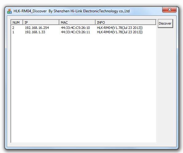
Connect the module WAN port to your home router using an RJ45 cable. The ” HLK-RM04_Discover.exe” tool will show the IP and MAC addresses for both the WAN and wireless ports. You should now be able to ping the device using “ping 192.168.1.33” to test the Ethernet port. If you get to this point you know that you have a working module and test bed. Now its time to make a backup
Backup the factory image
To create a backup of the original factory firmware I use a host application called FlashROM which works in concert with a client application running on the LPC1347. The default state of the LPC1347 after a reset is to leave the module on and enabled. If you login to the LPC1347 USB serial port you can issue an “f” command to start the FlashROM client. Remember to close the USB serial port after starting the client or FlashROM will complain that it can’t attach to the client port. From the Windows command line issue the following command to read the SPI flash and copy it to a file.
c:\msys\1.0\home\owner\flashrom>flashrom -p serprog:dev=com3:2000000 -r HLK_RM04_original.bin
Wait for the copy to complete which takes about three minutes. Save a few copies of the factory image for later use if you ever want to restore the module to its factory state.
Next
The next steps are to install Uboot and create a new OpenWRT image using Ubuntu running on a virtual machine like Virtual Box. Stay tuned….