 I decided to make a small PCB milling machine so that I could panellize the PCB boards I design. This is also an experiment in making a 3 axis CNC machine using a laser cutter. The preliminary work consists of defining a cutting pattern for tongue and groove joints that provide a tight friction fit along with a set of mechanical connectors that I could use as part of the construction. The mechanical connectors include a threaded T-nuts and using nuts and bolts in a laser cut slot to clamp the frame together. The entire machine is designed in Inkscape and is made from 6mm MDF.
My preliminary design results are very encouraging and while there are a few issues I am confident that I can come up with a workable design. I ordered an inexpensive 200W spindle motor to use with the machine and now that the part has arrived I can finalize the Z axis mounting design. I didn’t have any specifications for the spindle so I needed to measure the part to allow me to design the YZ axis
I am also developing electronics to control the machine. I have started to port GRBL (https://github.com/grbl/grbl) to an LPC1347 ARM processor but the code is not fully functional quite yet. Controlling the XYZ axis is relatively easy but designing a 300W spindle speed control will take a bit of work. I plan on prototyping the various component circuits separately and then when I have everything working I will integrate the designs into a single PCB. My goal is to develop a GRBL controller with the following features.
- 3 axis control
- 300W variable speed spindle control
- WiFi access
- isolated USB
- excellent thermal performance using integrated heat sinks
Finally I wanted to design a friendly cable management strategy for the CNC Cube. To help with this I have designed two PCBs. First there is an end stop limit switch which is mounted on 31mm centers (that is the Nema 17 mounting hole pattern) Second I designed a motor mounted PCB that allows me to run a single six conductor cable to each motor for control. The PCB terminates both the Nema17 motor and the limit switches for the axis. One cable per axis makes for a much cleaner design.
X axis
 I started by designing the X axis which is the simplest part of the machine. The working area of the machine is designed to be 10x10cm to accommodate my largest PCB, so I made the bed 15x15cm. The additional area at the edge of the X platform allows me to provide clamps for the PCB. I started by measuring the dimensions of the LM6U bearings and the long hex nut which moves the carriage. With the mechanical dimensions know I spaced the bearings and nuts so that the assembly would provide end stops to keep the mechanical parts in place.
The complex set of inserts creates a torsion frame to help make the bed very stiff. I intend to cover the top of the X platform two plates of 3mm MDF. The first plate would hold a series of 8-32 nuts while the second layer would be a waste board with clearance holes that make the nuts accessible. This means I have a bolt down plate to hold the PCB work piece in place while routing. The grid pattern for the nuts would be a 10 cm and 5 cm square to accommodate the typical PCB sizes I use.
YZ axis
 The Y and Z axis are combined into a single assembly to keep the axis as rigid as possible. The assembly of the Y axis is also a torsion frame just like the X axis. I have used four linear bearings on the Y axis to keep the axis from rotating under load. This design uses only a pair of LM6U bearings for the Z axis. I chose this option because it gives a larger Z axis movement.
Based on the results of my first prototype I wanted to shorten the Y axis height to give greater clearance over the X bed. This is a trade off because the wider bearing spacing gives better performance under torsion. That said, I still need to have the Y-axis clear the X-axis once I have the work piece and bit in place.
The Z-axis needed to be re-designed to support the spindle motor. The motor weighs in at 0.7Kg which is a lot heavier than I expected. The weight causes a small deflection in the Y-axis rails. I am now thinking 8mm rails would be better as they would be twice as rigid as the 6mm rails I’m currently using.
Frame
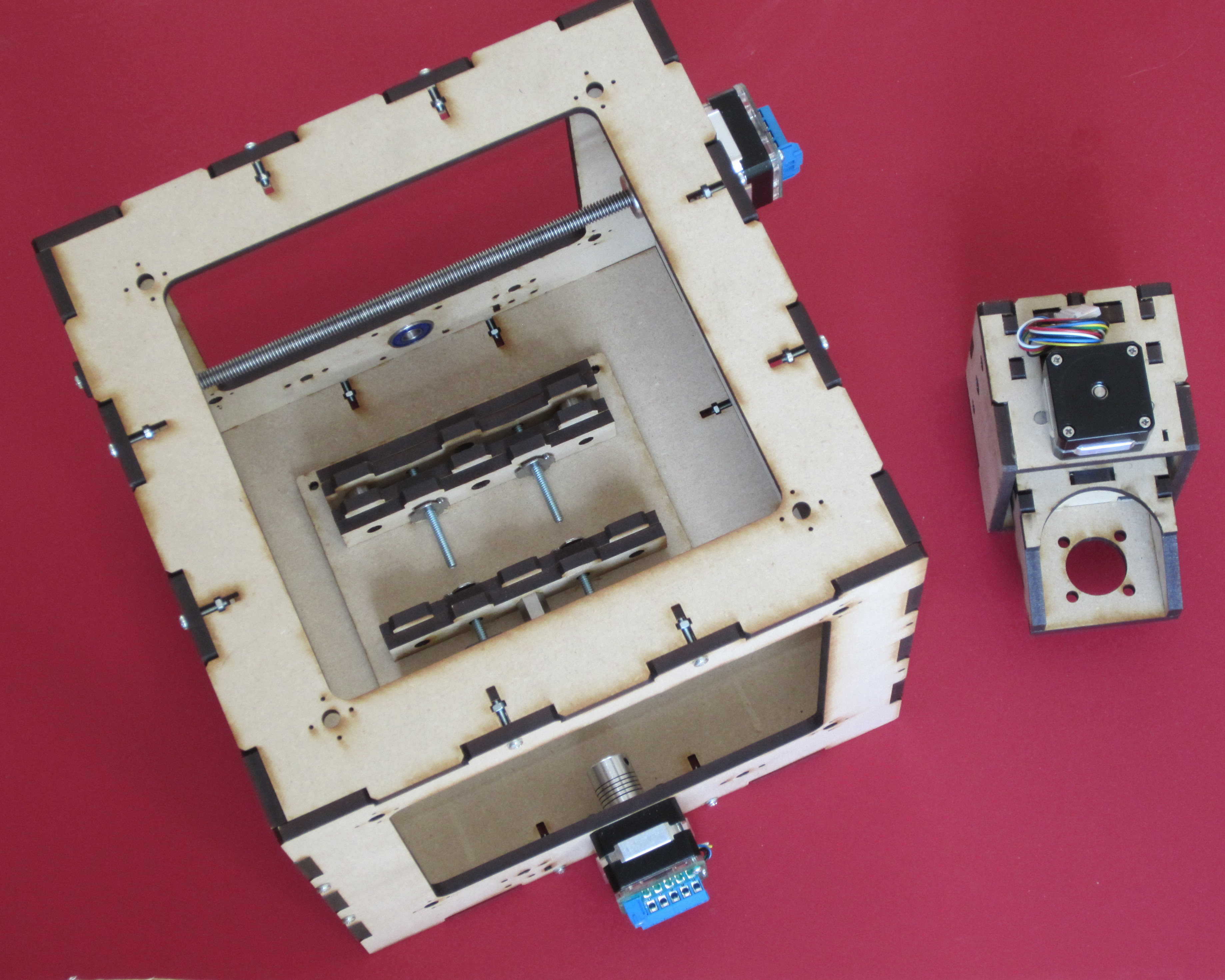
The CNC cube is constructed from a rigid outer frame that supports all of the CNC axis. The cubic shape keeps the machine compact and is very rigid while being simple to design. I mounted the X and Y Nema17 motors outside of the cube envelop which makes two sides of the design more irregular. This solution is simple but enclosing the motors within the frame would keep them from being damaged in transport.
The X and Y axis have been designed using a 15cm bed which only requires a lateral translation of +-7.5cm. The inner volume of the cube needs to be at least 22.5 cm in each dimension so I have chosen to go with a 25cm x 25cm x 25cm cube.
The outer cube has access windows to allow me to place work on the X table. The windows are equipped with T nuts in the corners so that I can seal them with clear acrylic windows. This is both a safety measure and it will help with dust control.
1 comment for “CNC Cube”