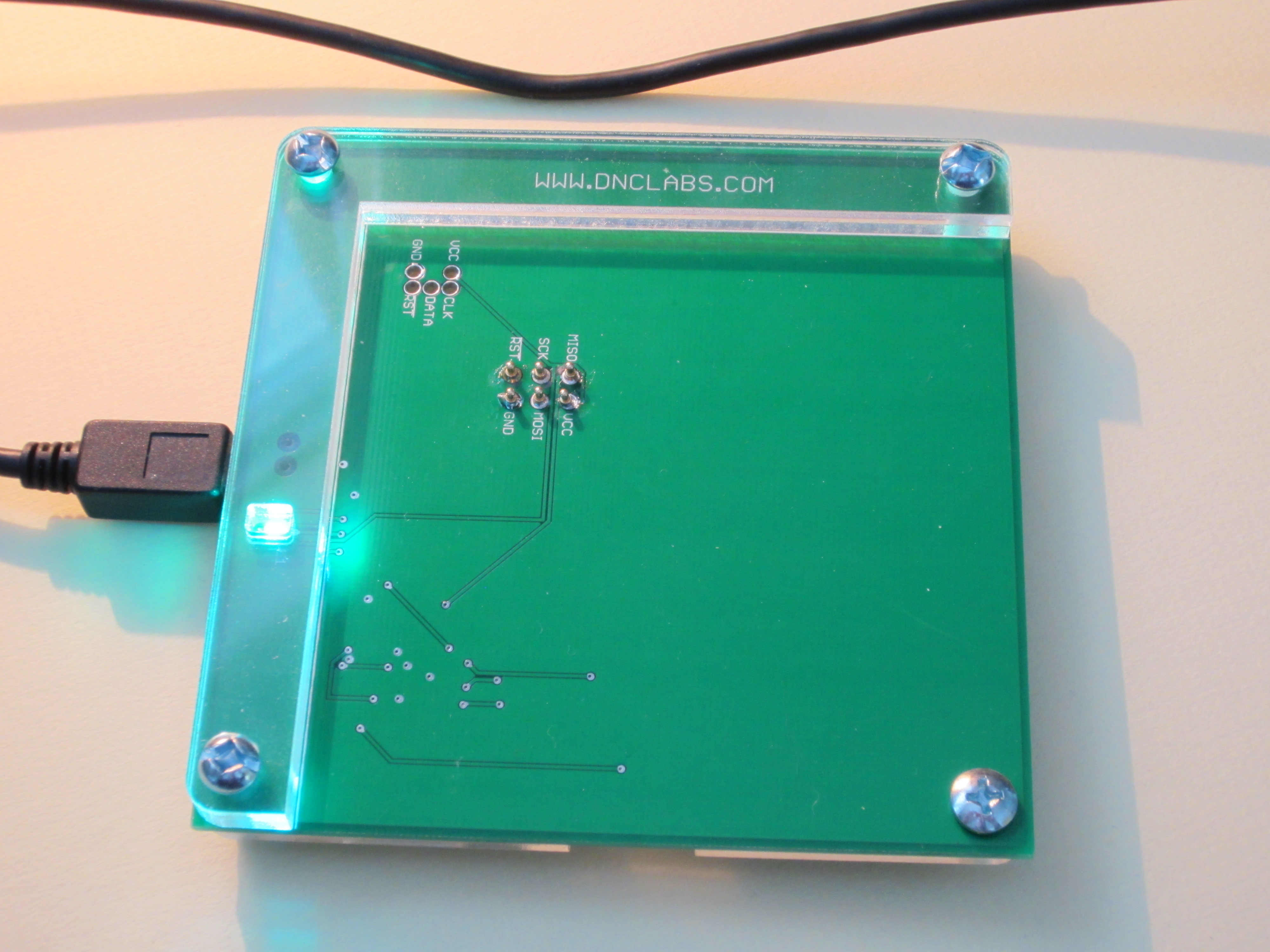
 I finally received the PCBs and plastic to put together my final design. If you have been following; this is my second version of the programmer and it is a much better design than my first attempt. Assembly takes about 15 minutes including soldering all the components. All of the connections are part of the PCB so the design is much more robust. The plastic packaging worked out very well and the addition of 8-32 mounting bolts with acorn nuts is a nice touch because it forms feet for the programmer.
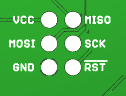 The programmer has two sets of pogo pin headers. One is for TPI programming while the other is for standard SPI programming. Simply by cutting new templates I can align any of my PCB design to work with this programmer. I now include a standard footprint programming header on the bottom of my AVR designs so that I can program the boards without the addition of any connectors. The bottom side view of the pad placement is shown here.
The MKII programmer code needed to have its revision code increased to 1.15 to satisfy AVR Studio 6. This change is included in the attached hex file. AVRISP-MKII.hex
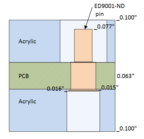
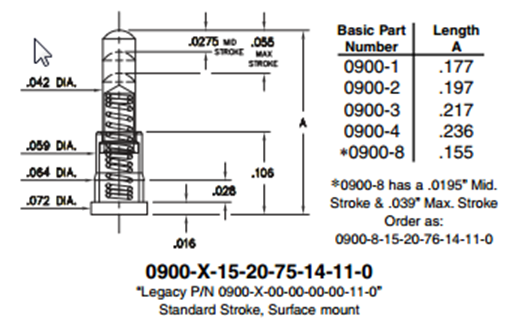
I also needed to select a slightly shorter pogo pin from Mill-max so that the plastic could be 0.1″ thick. Originally I was going to cut the plastic out of 0.25″ acrylic but then I found that SeeedStudio could cut my design out of 0.1″ acrylic for $7.50 for five 10x10cm pieces. The final design uses 2 layers of 0.1″ plastic for the top alignment frame so that I have a 0.2″ depth to support the PCB being programmed. While a single layer top support works, two layers is easier to use in practice. The single layer stack-up looks as follows.