 Building on the car project I have taken the pager motor and its paper supports and turned it into a linear actuator. So what is a linear actuator? Motors provide rotary motion that may not be useful in certain application. The ability to convert rotary motion into linear motion can be quite handy so I set out to design such a device, called a linear actuator. I will describe how I turned a pager motor into a small linear actuator.
I have easy access to low cost pager motors so all I needed was to design a support for the motor and threaded shaft. Since this idea is untested it will probably require a number of iterations to get to a workable solution. Using matte board and a Zing Laser I am able to rapidly prototype the parts to test different design options while not spending a lot of time or money on any particular test.
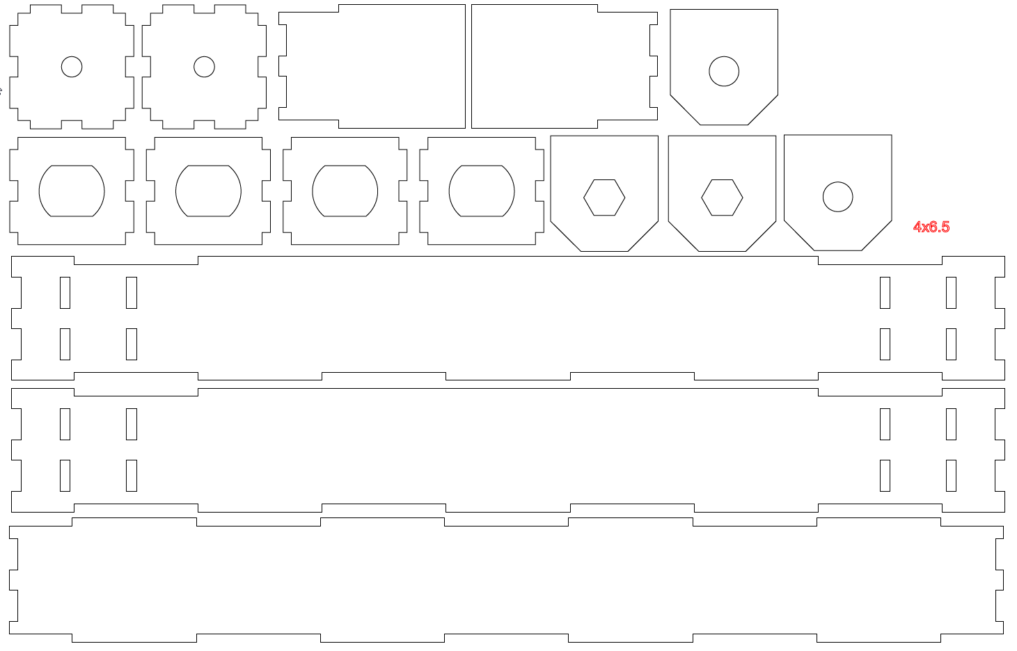
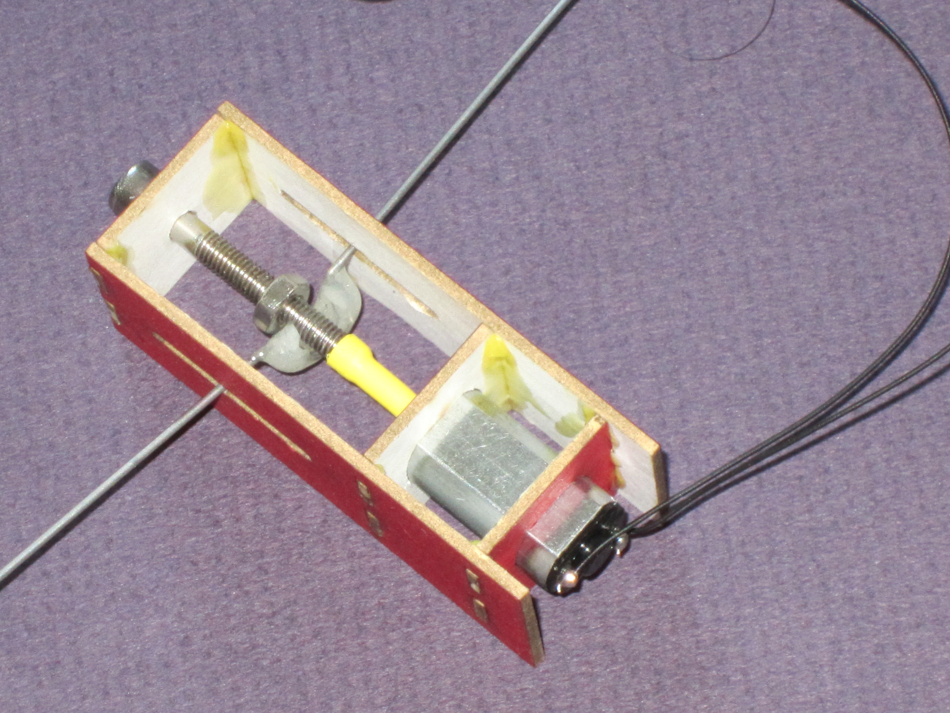
The frame for the actuator has been cut out of 0.05″ matte board. To make the unit more useful I have integrated all of the control electronics into the design. A thin film processor provides the computing power while a discrete H-bridge allows me to reverse the motor under program control. The actual mechanism to convert rotary motion into linear motion comes from a lead screw and nut. As the pager motor turns the lead screw the nut is translated linearly down the lead screw shaft. The nut needs to be held from rotating so I designed the paper frame to prevent rotation while allowing a push bar to slide up and down in a linear fashion. (The first trial shown in the picture used epoxy to connect the nut to the push bar but it broke very quickly so I moved to a paper nut holder).
The parts for the laser cut frame are shown here. They are glued to form a box and the pager and bolt are inserted into each end of the frame. To couple the 1mm motor shaft to the 3mm threaded bolt I used heat shrink tubing.
Assembly
To assemble the unit I epoxy the nut between three pieces of paper which forms a nut keep. At this point it is also a good idea to epoxy a 1″ push wire across the top of the nut keep. Once the glue dries I assemble the bearing end plate, threaded bolt and nut keep so that they are threaded together. Insert the motor into its mounts and align the spacing so that they fit easily into the edge frame. When you have a good dry fit it is time to glue the entire assembly together with wood glue. It is important to tack glue the motor in place or else the motor torque will push it out of place while in operation. The threaded bolt is coupled to the motor shaft with heat shrink tubing that is applied after the glue has dried.
Take two
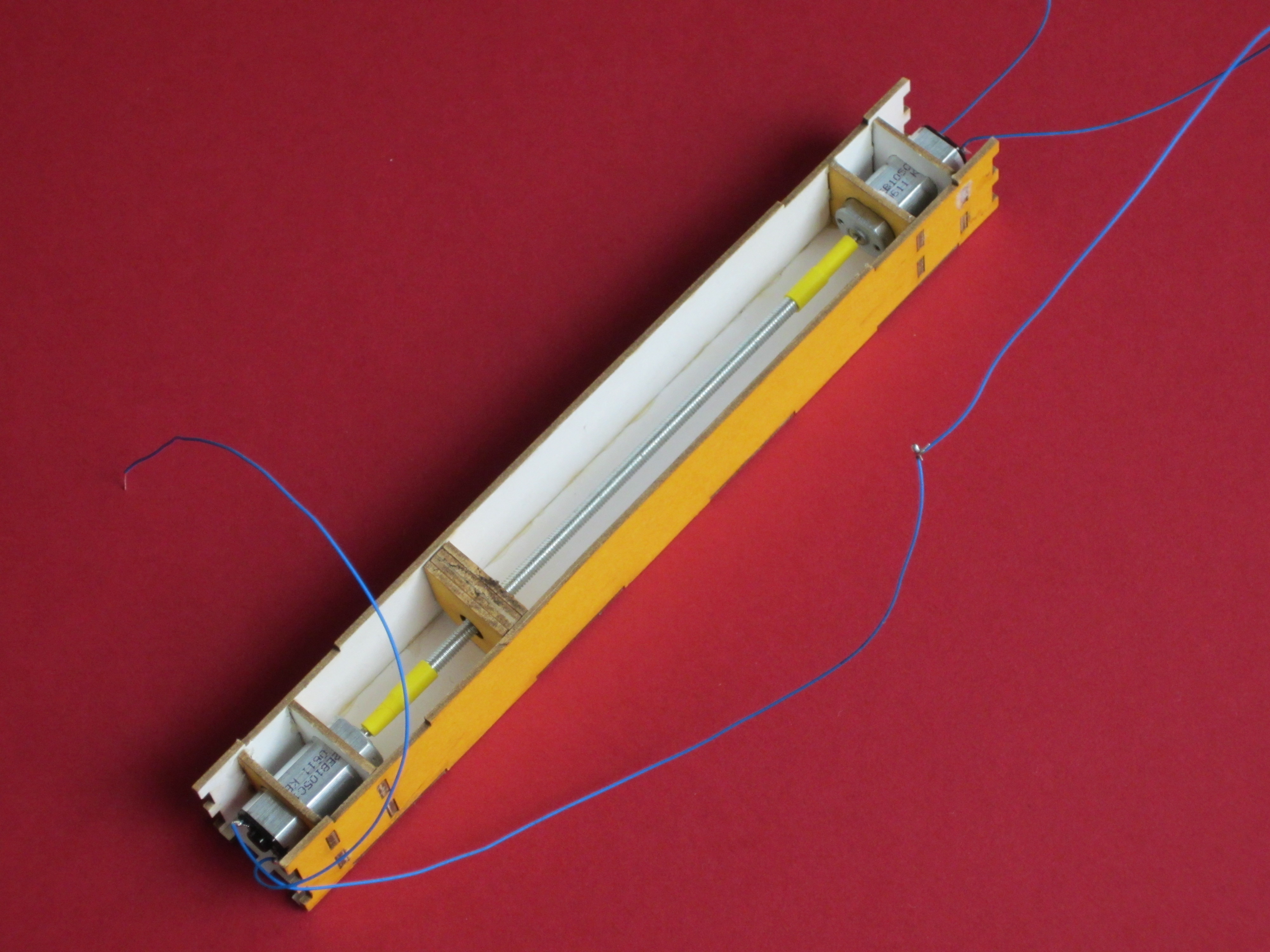
My first test of the actuator revealed a few issues. Initially I had connected the motor shaft to the threaded rod using heat shrink tubing but I found the connection to the motor tends to slip. The other significant issue is the limited torque that the motor provides. When the nut is free running the torque is sufficient but if the nut collides with an end stop it binds and there isn’t enough torque to free the nut. I need some form of sensor to keep this from happening. Also in the initial design there is only one motor so to reverse direction I need to flip the power leads to the motor. To accomplish this under computer control requires an H bridge, but I opted to use two motors in the second design instead of adding circuitry. The very low cost of the motor made this a simple solution. If I do add an H-bridge I can also benefit from the additional torque provided by two motors.
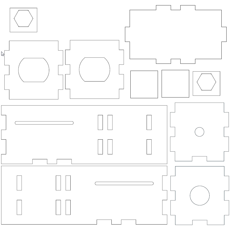
The new design uses two motors and a new laser cut coupler that is glued to the shafts with loktite. I haven’t addressed the nut binding issue with this design but I am one step closer. This is a work in progress and still has a number of issues that require further testing and design.