This is my first look into the possibility of creating a simple computer circuit built of paper and copper foil. The design actually supports a complete Arduino sketch environment and costs less than $2 to build. So lets get started.
Capturing the design
I began by drawing my circuit using Eagle. Eagle is a circuit schematic editor that is widely used by hobbyist to capture schematic designs that will be manufactured as traditional PCB’s. I decided to use it because it would automate drawing the circuit layout and give me a clean schematic of the circuit. The basic design of the Tiny44 Paper Arduino is shown here.
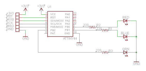
As you can see I have connected 6 pins for programming and powering the circuit. I also added three LED’s to the circuit so that I could experiment with the chips programming capabilities. The ATtiny44 chip only has 4K of Flash memory which is significantly smaller than the typical 32K supplied by Arduino Uno, however it should be adequate for this type of blinky LED circuit.
Routing the circuit
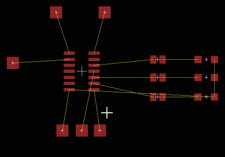 Once the schematic was captured I switched to the board view and placed the components. The yellow lines show air wires indicating the connections that need to be made. I place the components to keep the layout from requiring the air wires from crossing since a crossed wire would be harder to build without resorting to double sided circuitry. Since we are building a paper circuit simpler is definitely better. Once I was happy with the placement I clicked the auto router and set the routing so that it only uses one side of the board. Again this simplifies the actual assembly later.
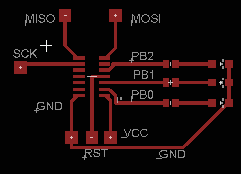
The results from the auto-router looked great since the design only required a single layer of copper as shown. As you can see I also added top layer text to make the design a little more readable. At this point I want to export the design to work on it further using Inkscape. To accomplish this I use the print command from the board view and have it printed as a pdf file. Make sure that the scaling is 1:1 because we need an accurate placement for laying down the copper tape.
 At this point you could have just printed the design to paper and started to lay down copper tape but I wanted to add a few details to the printed design so I import the pdf file into Inkscape. In particular I wanted to thicken the traces to 0.25″ since that is the nominal width of the copper tape. Where 0.25″ is too wide I use 0.125″ which only requires me to cut the copper tape in half length wise. You can see the final results of the design to see what I mean.
The imported pdf file becomes a template that I draw over to create my final tape layout. The very last step is to delete the pdf template since it just gets in the way. I created the tape outlines as rectangles rather than lines because this gave me nice square ends to work with for aligning design elements. The first piece of work was to create the pad outlines which was a simple matter of drawing a rectangle over one of the pdf design pads and then replicating and placing it until all of the pads were complete. Its a good idea to group the component pads since there spatial relationship is critical.
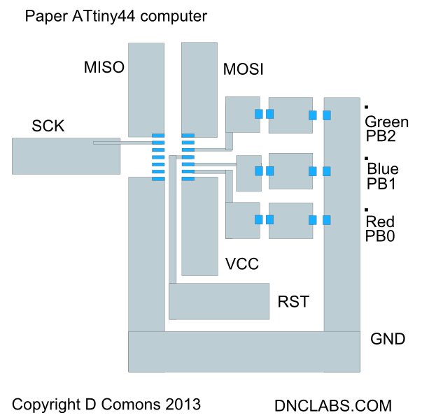 As you can see, where possible I used 0.25″ tape. This minimizes cutting but it also is more secure because the glue area is larger so it sticks to the paper a little better. I found that it was better to use a light colour to fill the rectangles because the tape tends to peel off if I use highly saturated black fills. The completed design is then saved as both an svg and pdf file. I like the pdf as a final design file because anyone can print it while the svg can only be printed if you have Inkscape installed. So that’s it for designing the circuit.
Assembling the circuit
The next step is to cut and lay down the tape. I start by printing the design on 24lb paper which is just a little bit stiffer than typical laser paper. The advantage of the slightly thicker paper is that it curls less after the copper tape is applied. I bought the copper tape from Digikey part # 3M1181A-ND (18 yards for $18). The assembly is simple you just cut copper tape to cover the printed traces. Note that wherever two pieces of tape cross one another like in the lower right corner; you will need to join the circuits with solder. This is because the copper tape is only conductive on the metallic top side while the sticky acrylic tape is actually an insulator. To ensure connectivity I bridge the circuit by spot soldering. In case you missed it; it is better to have a continuous piece of copper rather than over lapping copper because it saves a solder step.
Once the copper tape is entirely glued down it is time to solder the components down. This is a lot easier than you would think. I usually start by soldering the processor in place make sure none of the lead pins is shorted. Then I drop down the resistors and finally the diodes. A note about the diodes, they are polarized and the end of the component with the green dot must be connected to ground. Finally I go over the circuit and tack solder any points where the copper tape crosses itself and your almost done. I would recommend checking the pad to pin connectivity with an ohm meter to make sure everything is connected.
I used wire wrap wire to bring the ISP pins to a 1×8 header so that I could program the design. I just tack soldered both ends of the wire to the paper circuit and to the connector. This allows me to plug the circuit into an Arduino for programming.
Setting up a tool chain
In order to program the chip I had to add a new board to the Arduino environment. I did this by opening the ~\arduino-1.0.3\hardware\arduino\boards.txt file and adding the following lines to the top of the file.
attiny44.name=Paper Computer Tiny44
attiny44.bootloader.low_fuses=0x62
attiny44.bootloader.high_fuses=0xdf
attiny44.bootloader.extended_fuses=0xff
attiny44.upload.maximum_size=4096
attiny44.build.verbose
attiny44.build.mcu=attiny44
attiny44.build.f_cpu=8000000L
attiny44.build.core=arduino:arduino
attiny44.build.variant=Tiny44
Next I created a directory called Tiny44 in the ~\arduino-1.0.3\hardware\arduino\variants directory and copied this pins_arduino.h file to the directory so that the pin definitions for the board were available in sketch.
Setting up AVR MKII programmer
I wanted to be able to compile and run code from either sketch or AVR Studio however there were a few technical hurdles to over come. First sketch uses Avrdude’s libusb drivers as the host driver to talk to the MKII programmer while Studio uses Jungo drivers. To allow both to co-exist I loaded up the AVR Studio environment and let it define the USB drivers as being supplied by Jungo. Next I downloaded the latest version of libusb filter drivers from http://sourceforge.net/apps/trac/libusb-win32/wiki. Plug in your MKII programmer or Lufa MKII clone and then run the install-filter.exe to allow you to add the libusb drivers required by Avrdude. The libusb drivers provided by Arduino don’t include the filter driver so you need to manually add this as described.
The second problem I encountered was that when I tried to download a design from sketch to the paper circuit it would just hang. I am using the Lufa MKII clone as a programmer. To resolve this issue I downloaded the source code for avrdude5.11 from http://download.savannah.gnu.org/releases/avrdude/ and edited the usb_libusb.c file at line 442 I added.
static int usbdev_drain(union filedescriptor *fd, int display)
{
/*
* On some USB devices (specifically LUFA based AVRISPmkII’s
* this actually causes a problem and doesn’t appear to be
* required on USB anyway.
*/
return 0;
I recompiled the code and had a patched version of Avrdude that will work with the Lufa MKII programmer. One last detail I had to replace the Arduino version of Avrdude with my new version. I replaced ~\arduino-1.0.3\hardware\tools\avr\bin\avrdude.exe with my new version.
Results
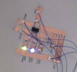 Was it worth it? Definitely. I had a lot of fun building this circuit and the ease with which I accomplished this should allow me to try some more artistic possibilities. I love the low cost and the fact that anyone who can use an Arduino can start building two dollar paper circuits which is a far cry from the $30 full fledge Arduino board. I also think that the use of Eagle as a tool allows you to become familiar with circuit design and paves the way to finally ordering real PCBs since you have effectively captured a complete PCB ready circuit.