I’m not sure whether this design should be called Carduino or Swarmbot. The design of this car is based on the Arduino UNO where the pin map matches that of an UNO. The design includes a dual H-bridge so that the motors are individually reversible. I have also included an IR remote control to send messages to the vehicle. Unlike previous paper car designs I have designed a 3D printed body that holds the entire vehicle together. In previous designs I was trying to minimize cost so I selected processors with less capabilities; in this design I have included an UNO capable design so that the vehicle looks like an UNO when programming the car. Making the vehicle UNO compatible means that it is self programming over the USB connection and allows you to directly use the large library of existing UNO code.
Initial specification:
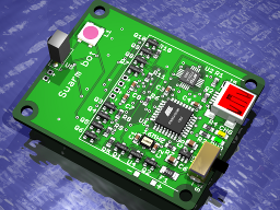
- FTDI and ATmega328 UNO core processor
- 240mAhr 3.7V LiPo with USB charger, and under voltage protection
- Dual H bridge to drive two pager motors
- IR remote control
- 3D printed body
- Extra I/O are brought to solder pads (allows sensors to be added)
- 3D Plastic wheel hub with rubber tires
I have deliberated a lot over the battery design for this car but I finally decided to use a Lithium Polymer battery with a charging circuit. The concern with this choice is; the LiPo batteries can catch fire if mishandled and they have a nasty habit of melting wires if they are shorted. To make this choice acceptable I have enclosed the LiPo battery entirely within the vehicles plastic body to reduce the risk of short circuits. I have also fused the battery to limit the burnt wire problem.
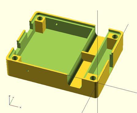 So what does the car look like? It’s a small 42x52x13mm design packaged in a plastic case. The PCB and body are bolted together and this is used to clamp the motors in place. The design has two wheel drive and uses 3/4″ O-ring gaskets to create rubber tires. On the front of the vehicle there are two electrodes that can be used by the robot to charge itself. The charging system will allow you to create feeding stations so that the vehicle could be programmed to seek out charging stations to re-charge itself. I am still getting a little bit of warp in the 3D part so I expect this to change in the next iteration.
Schematic
The car design consists of an ATMega328 U1 and FTDI USB U2 to serial chip to provide the Arduino UNO interface. I extended the design by including a LiPo battery charger based on the MC73831 U3. The charger is simple but to ensure that the battery is not damaged due to under voltage I included additional protection hardware. The under voltage protection uses a 3V reset circuit U4 to detect when the battery voltage has dropped below three volts. The output of the reset chip is inverted by Q2 and fed to the P-channel power FET Q1. The P-FET effectively turns the circuit off when the voltage battery is too low. The circuit will only recover after the battery is recharged above 3V.
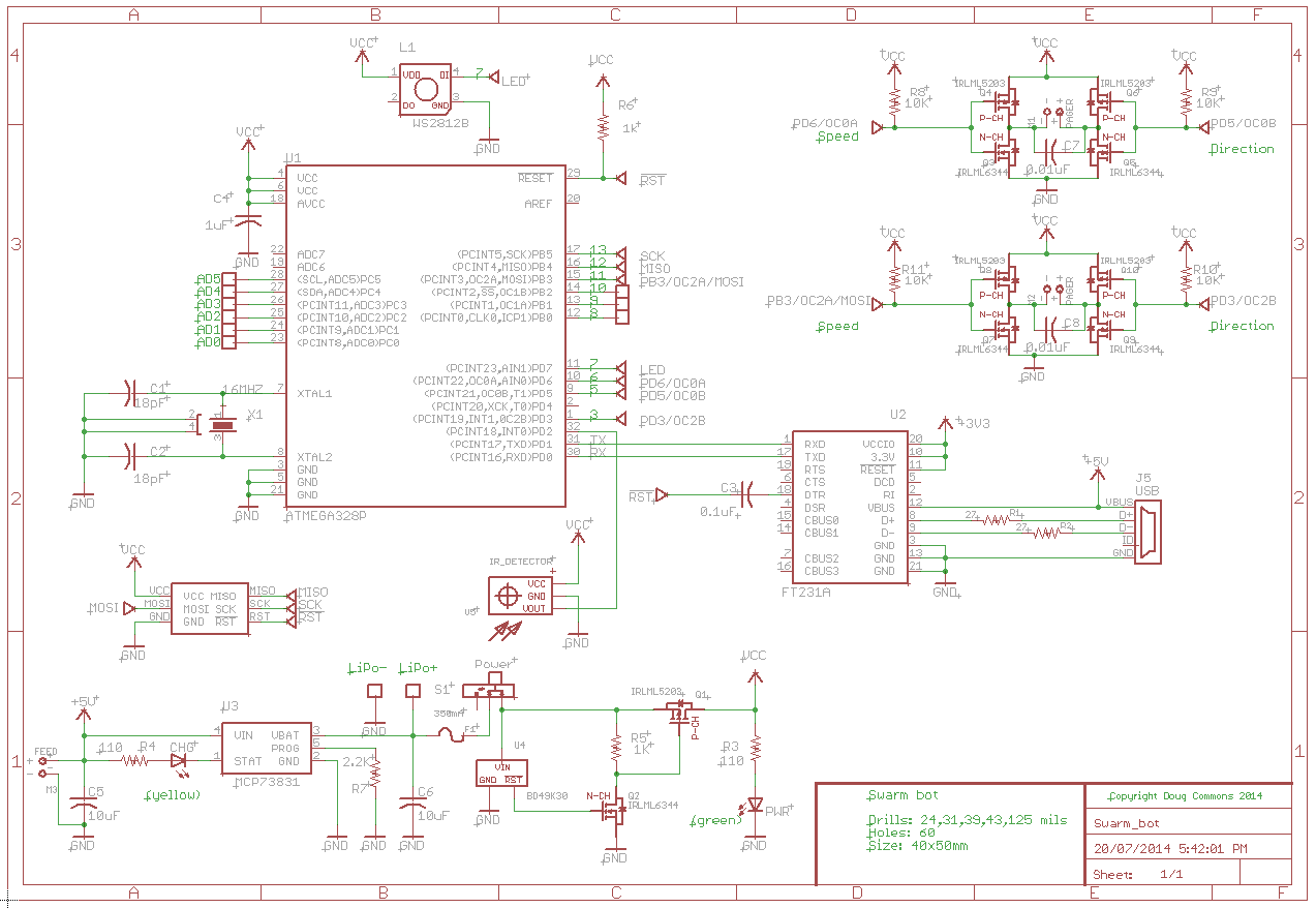
I had hoped to set the polyfuse current to trip at 250mA but the motor inrush current caused a 1V drop in the supply rail. The noise introduced by the fuse adversely effects the microprocessor and WS2812B resulting in random brownouts. To correct this I moved to a 500mA fuse which introduces a greater risk of melted wires if the circuits are shorted.
The H-bridge circuit is implemented using discrete FETs. It is important to switch each leg of the bridge quickly as there is a slight shoot through when both the high and low side drivers are in transition. The 10K pull ups on the FET gates ensure that the transistors are fully on or off when the processor is in a reset state and the gate drive is floating. Without pull ups the motors would come on randomly and the risk of turning both the high and low side drivers partially on is very real. The consequence of leaving out the pull ups is fried FETs and magic smoke.
Next Steps
I need to develop a low cost LED line sensor array for the bottom of the car. I also need to figure out when the motors are stalled so that I can detect collisions. When the motors are turning they generate a back EMF which can be used to determine the motor speed. If the car hits something and stalls the motor the speed drops to zero, as well the back EMF drops to zero. I want to wire two of the ADCs to each of the two motors so that I can detect the change in voltage. I also suspect that the commutation closures can be used as a speed encoder so that I can actually measure the wheel speed and not just collisions that stall the motor.