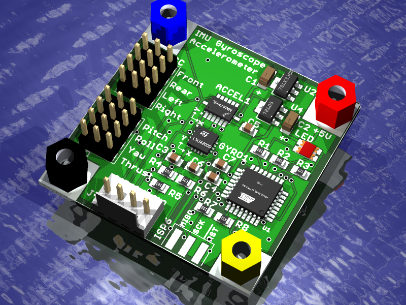
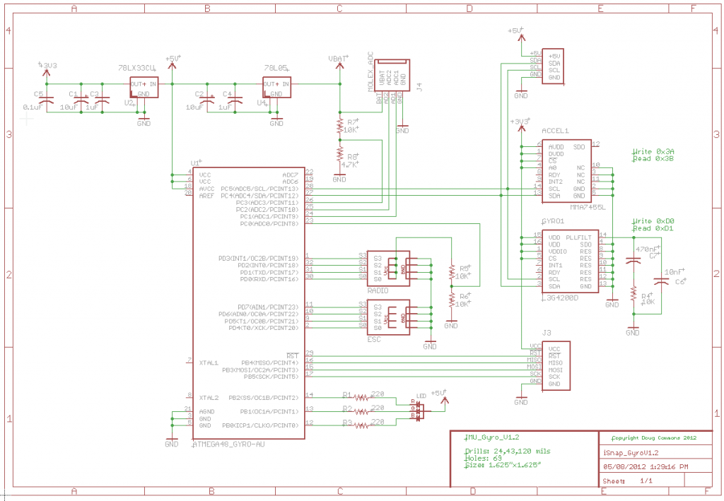
The sensor board provides a 3.3V 6DOF sensor system which includes an accelerometer and gyroscope. The physical sensors are the L3G4200D gyroscope and MMA7455L accelerometer which are described in detail in the associated datasheets. This board also terminates the radio and ESC PWM signals which are ~5V so the ATmega48 is run at a nominal 5V. The electronic speed controllers are driven by timer interrupt routines that generate the four pulse width modulated signals. The ATmega48 appears as an I2C slave device that the LPC1769 core board can see. The LPC sends commands to the ATmega48 to control the level of each ESC channel. The ESC values are programmed from 0 to 100% and there is a unique I2C register for each ESC. So that there is a decent level of resolution the I2C registers are 16 bits wide. Of course the LPC1769 could have used its internal PWMs to do this but I wanted to decouple the ESC control from the core processing in preparation for custom I2C ESC’s.
One of the performance limitations of this board configuration is the I2C bus. At 100kHZ the 10bit transfers take 10uS each so addressing and reading a 16 bit register will take 30uS. This doesn’t sound to bad but when you add up all of the accesses things start to slow down. A full loop of the code reads the gyroscope 30us + accelerometer 30uS + 4*motors 30uS + 4*PWM 30uS + LED 20uS + battery 20uS = 340uS. Of course this limits the design to 3K samples per second but this is alot faster than the typical sample rate of say 250 samples per second.
Similarly the M48 measure the radio receivers PWM output to determine the pitch, roll, yaw and thrust. The pin change interrupts on the AVR are used to detect edge transitions that are timed by a 16 bit timer. The LPC1769 can then query the M48 to determine the current radio setting.
For house keeping the M48 has been equipped with a tri-coloured LED and is capable of measuring the main battery voltage along with the radio receivers battery voltage. This allows the LPC1769 to flash out signals over the LED and to determine the battery state for error handling.
The board uses two linear regulators to generate 5V and 3.3V from the battery supply. This board terminates the LiPo battery circuit and provides 5V to the entire board stack including the core processor.

