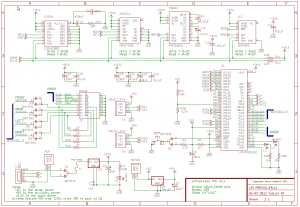
To get started I bought an LPCExpresso 1769 board for the core processing. It was inexpensive at $30 and the design allows the board to be cut in half so that the in circuit emulator half of the board can be used to program other ARM processors. To provide the quadracopetr with sensors I built a daughter board that provides a magnetometer, pressure sensor, gyroscope and accelerometer. Additionally the board provides a termination point for the radio control and 4 ESC’s. The Turnigy electronic speed controllers are rated at 25Amps and drive four brushless DC motors. A friend built the air frame but most of my testing to date has been on a test bed.
In the schematic most things are obvious but the ESC circuit uses a lot of diodes to level shift the 3.3V LPC1769 outputs to the ~5V level used by the ESC’s. It works by enabling the LPC’s outputs to operate as open collector. The outputs are then isolated from the ESC by diodes so that no voltage flows out of the LPC, instead the ESC’s are driven by the pull up resistors. A low on the LPC output pulls the output low via the diode while the pull up resistor current limits the inputs.
I have written a lot of test code for this set up but I haven’t actually got the quadracopter in the air yet. The sensor control system is complete and works well giving and error of about 1.5o even after severe acceleration. The algorithm consists of a first order complimentary filter that merges the gyroscope and accelerometer readings into a high quality reference angle. At this point after about a year of on again and off again work I am at the point where I want to migrate to new hardware. This is particularly import in view of the fact that my test bed needs to be re-built because the bearings have become misaligned and I need a second motor in the test set up.
