 The ability to compile a completely new custom Linux kernel makes it easy to create devices based on the HLK-RM04 module. There are many software packages that are available as part of OpenWRT. Once you can compile your own kernel you have the option to add your own custom code to the build. Building a kernel is straight forward but for the first time user the configuration options are overwhelming. First we need to configure the kernel so that it recognizes the amount of SDRAM memory we have installed on your module. Next we configure the Linux image so that it builds code for the RT5350 system on a chip.
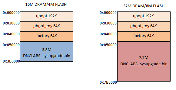
There are two memory limitations that you should be aware of when building a kernel. First the compressed Linux image needs to fit onto the SPI FLASH which can be either 4M or 8M depending on which module you purchased. Note that 192K is reserved for the Uboot loader while two 64K blocks are reserved for parameters like the MAC address, so the image needs to fit in 4M-320K or 8M-320K depending on the module. This limitation is most important for the 4M configuration because it limits how many applications you can install at boot time. I have actually cut out a few less useful options to give me more space. The second memory limitation is the size of the SDRAM. With only 16M you are quite limited in what you can do so I would recommend spending a couple of dollars more to get the 32M module.
Once we finish configuring the packages to be built we still have a few configuration options to deal with. The default state of the Linux OS running on the module needs to be defined. There are configuration files that show up in the Linux build but their default values are not very useful. To solve this I add a directory named “files” to the openWRT root directory. The content of the “files” directory is copied to the kernel image so it shows up on our freshly built module. This feature allows me to define the wired and wireless network configuration as well as setup a web interface. You can always manually configure a module using the VI editor but over time having this as part of the build will be easier. I usually manually create a working configuration and then I copy the config files back to the “files” FILES.ZIP directory so they get re-built any time I re-compile the kernel.
Installing Openwrt source code
To get started we need to install the openWRT source files on our Ubuntu host computer. The source code directory is created using the following commands.
cd ~/Desktop
git clone git://git.openwrt.org/openwrt.git
cd ~/Desktop/openwrt
./scripts/feeds update -a
./scripts/feeds install ser2net
./scripts/feeds install avrdude
make menuconfig
make -j7
When you run make menuconfig and make you will create a cross compiler and default linux image. The first build is very slow since the entire compiler tool chain must be built. This can take several hours so be patient. Subsequent builds are faster as only new packages need to be compiled. Next we will tweak the source code to customize the openwrt build for our own needs. You can start by copying the “files” directory to the openwrt directory (~/Desktop/openwrt).
You will need to edit the wireless and network config files to configure the modules IP address for your home network. I described this process in “Step 2 Install OpenWRT” blog entry.
After compiling the default image for the first time, I alter a few configurations to produce a useful base image. I need to add these changes after the first build so that the options show up in menuconfig. Copy the files from DNCLABS.ZIP to the directories as shown. This will customize your openWRT source tree for the HLKRM04. DNCLABS.ZIP
openwrt /target/linux/ramips/base-files/lib/ramips.sh
openwrt /target/linux/ramips/image/Makefile
openwrt /target/linux/ramips/rt305x/profiles/dnclabs.mk
openwrt /target/linux/ramips/dts/dnclabs.dts
openwrt /target/linux/ramips/dts/rt5350.dtsi
openwrt / rm -rf tmp
These changes configure the hardware specifically for this project. I have also tweaked the device tree structure( DTS file) to match the physical hardware of the HLK-RM04 module. This initial setup has only created the source files we need to build our image. From here we need to select the kernel options and linux options that we want to build. In the next sections we will configure the build.
Kernel Memory Configuration
Based on the HLK-RM04 module you purchased the kernel needs to be configured differently. The HLK module is equipped with either 16 or 32M of SDRAM and uses hardware jumpers to detect the memory size. The Hi-Link module jumpers are always set to read 32M even when only 16M is installed so we need to tell the kernel the memory size. This can be done using the kernel configuration console.
make kernel_menuconfig
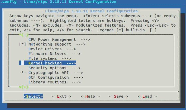
find kernel hacking, press Enter and then find (rootfstype=squashfs,jffs2) Default kernel command string
press Enter again and manually set SDRAM value rootfstype=squashfs,jffs2 mem=16M (or mem=32M)
Exit and save the configuration.
For a 16M SDRAM, 4M of SPI flash module
rootfstype=squashfs,jffs2 mem=16M

For a 32M SDRAM, 8M of SPI flash module
rootfstype=squashfs,jffs2 mem=32M

Openwrt configuration
To configure openWRT features you can use a graphical tool called “menuconfig” that allows you to include or exclude features from your target image. Open a terminal window in the openWRT install directory . The features I have included and excluded are as follows.
make menuconfig
Configure HLKRM04 target
Target system
	Ralink RT5032 ---RT3x5x/RT5350 base boards
	Target Profile
		DNCLABS
Remove packages
To save space on a 16M module I remove these packages from the build. They can be added back if you need them for some reason.
Base system
	dnsmasq
	firewall
	opkg
Kernel Modules
	Network support
		kmod-ppp
Network
	Firewall
		ipv6tables
	odhcp6c
	odhcpd
	ppp
	Web Servers/Proxies
		uhttpd
Save and exit the menuconfig utility. Then build your image with the following command.
make -j7
The -j7 needs to match the number of processors you have on your Ubuntu machine. The number is set to the number of CPUs +1 (in my case a 6 core machine plus one).
Once the openWRT image has been built you can go back to my blog entry step 2 and install your own freshly built image on the module.
OpenWRT Overview
Initially I found it difficult to find files and directories that I needed to change while configuring my Linux builds. To help others I have provided a brief description of the file hierarchy. With so many directories and files it was like looking for a needle in a hay stack to find where changes needed to be made. In the end it turns out I only really needed to worry about three directories and a few files.
Image generation
The “bin/ramips” directory contains the linux image after the make command completes. The DNCLABS-sysupgrade.bin file is the new image that we will TFTP transfer over to the module. Notice that the linux image is in the file named openwrt-ramips-rt305x-dnclabs-squashfs-sysupgrade.bin which I truncate to dnclabs-sysupgrade.bin before downloading it to the module.
openwrt-ramips-rt305x-dnclabs-squashfs-sysupgrade.bin
![]()
bin – where the final Linux image resides after a successful build.
ramips – is the RALINK MIPS architecture that the HLK RM04 uses
Files
The files directory is added to the openwrt source tree to provide feature customizations that are built into the image file. The “files” directory contains a set of files that will get copied to the final compressed Linux image. I have setup /etc/config/network and /etc/config/wireless files to pre-configure the module so that it connects to my network. I also added a web interface and WS2812B driver and code here.

/files/etc – contains the default configuration for your applications as well as providing a splash banner file when you boot. The avrdude.conf file is an abbreviated config file that allows you to load code into an Arduino UNO over the uartf serial port.
/files/etc/config – each of the network peripherals needs to have its interface defined. These files allow you to setup your IP address, SSID and the type of access (client or host).
/files/usr – this directory contains any code you want to install on the module. This is typically you own code written in ‘C’.
/files/www – The web server looks in the www directory to find its HTML source code so this is an ideal place to create a custom web interface.
The “temp.txt” file is generated the first time you run “make” If you want to change the option presented in “menuconfig” this file can be removed so that this file is re-built with any changes you have made. The command line instruction is:
rm -rf temp.txt
The “build_dir” is the heart of the compilation. The files in this directory form the final Linux image when compiled.
Tools
OpenWRT builds a cross compiler for the target architecture you specified when you ran the menuconfig command. The following folders are associated with the cross compiler. You shouldn’t need to edit or modify these files.
![]()
tools -contains all the build instructions for building the cross compiler.
toolchain -contains the kernel headers, the C library, the bin-utils
include – header files
scripts – perl scripts that manage the openWRT packages
staging_dir – where the cross-compilation tools are installed
Feeds
OpenWRT builds itself by downloading its source code from a code repository maintained by the openWRT community. The feeds.conf.default file in the root directory defines the location of these web repositories.

feeds – internet files that can be downloaded to add features to Openwrt.
dl – user packages are downloaded here
package – the openWRT makefiles and patches for all of the main packages. OpenWRT uses a custom “make” syntax. The makefile defines meta information for each packages ie)where to download the package, how to compile, where to installed the compiled binaries.
target -build instruction for firmware image and kernel build process; compiles kernel and firmware image utilities, builds firmware image
Device Tree Structure
The device tree structure defines how the physical hardware will be allocated. The HLK RM04 module has a limited number of I/O pins that are brought out to connector pins. The device tree structure allows us to define how these pins are to be accessed. The location of the DTS file is buried deep in the target directory as shown.

Setup
The DNCLABS.dts file is modified to support the HLK SPI flash type to fix this error
[ 0.470000] m25p80 spi32766.0: found w25q32, expected s25fl064k
[ 0.490000] m25p80 spi32766.0: w25q32 (4096 Kbytes)
The DNCLABS.dts file is modified to support fewer GPIO consistant with the HLK
The 16M HLK-RM04 uses an 4k flash while the 32M HLK-RM04 uses a 8K flash so we fix this as follows:
partition@50000 {
		label = "firmware";
		reg = <0x50000 0x3b0000>;
		};

or

partition@50000 {
		label = "firmware";
		reg = <0x50000 0x7b0000>;
		};
The DTS file that I use is as follows:
/dts-v1/;

/include/ "rt5350.dtsi"

/ {
	compatible = "DNCLABS", "ralink,rt5350-soc";
	model = "DNCLABS";

	palmbus@10000000 {
		gpio1: gpio@660 {
			status = "okay";
		};

		i2c@900 {
			compatible = "link,rt3052-i2c";
			reg = <0x900 0x100>;
			#address-cells = <1>;
			#size-cells = <0>;
			status = "okay";
		};

		spi@b00 {
			status = "okay";

			m25p80@0 {
				#address-cells = <1>;
				#size-cells = <1>;
				compatible = "mx25l6405d", "s25fl064k";
				reg = <0>;
				linux,modalias = "m25p80", "s25fl064k", "mx25l6405d";
				spi-max-frequency = <10000000>;

				partition@0 {
					label = "uboot";
					reg = <0x0 0x30000>;
					read-only;
				};

				partition@30000 {
					label = "uboot-env";
					reg = <0x30000 0x10000>;
					read-only;
				};

				factory: partition@40000 {
					label = "factory";
					reg = <0x40000 0x10000>;
					read-only;
				};

				partition@50000 {
					label = "firmware";
					reg = <0x50000 0x7b0000>;
				};
			};

			spidev@1 {
				compatible = "linux,spidev";
				spi-max-frequency = <10000000>;
				reg = <1>;
			};
		};

		uartlite@c00 {
    			status = "okay";
		};

		uart@500 {
   	 		status = "okay";
		};
	};

	pinctrl {
		state_default: pinctrl0 {
			gpio {
				ralink,group = "jtag", "led";
				ralink,function = "gpio";
			};
		};
	};

	ethernet@10100000 {
		mtd-mac-address = <&factory 0x4>;
	};

	esw@10110000 {
		ralink,portmap = <0x17>;
	};

	wmac@10180000 {
		ralink,mtd-eeprom = <&factory 0>;
	};

	ehci@101c0000 {
		status = "okay";
	};

	ohci@101c1000 {
		status = "okay";
	};

	gpio-export {
		compatible = "gpio-export";
		#size-cells = <0>;

		gpio0 {
			gpio-export,name = "gpio0";
			gpio-export,direction_may_change = <1>;
			gpios = <&gpio0 0 0>;
		};

		/* ETH LEDs */
		gpio25 {
			/* ETH3_LED */
			gpio-export,name = "gpio25";
			gpio-export,direction_may_change = <1>;
			gpios = <&gpio1 3 0>;
		};
		gpio26 {
			/* ETH4_LED */
			gpio-export,name = "gpio26";
			gpio-export,direction_may_change = <1>;
			gpios = <&gpio1 4 0>;
		};
	};

	gpio-leds {
		compatible = "gpio-leds";
		status {
			/* UARTF_RXD */
			label = "dnclabs:green:status";
			gpios = <&gpio0 10 0>;
		};
		eth {
			/* UARTF_DTR_N */
			label = "dnclabs:orange:eth";
			gpios = <&gpio0 11 0>;
		};
	};
};
Pin map
UARTLITE(2) TTYS1 (Connected to the USB to serial converter on test board.)
GPIO16 – RXD2
GPIO17 – TXD2
UARTFull(5) TTYS0
GPIO7 – RTS
GPIO8 – TXD
GPIO9 – CTS
GPIO10 – RXD
GPIO14 – RIN
I2C(2)
GPIO2 – SCK
GPIO3 – SDA
GPIO(1)
GPIO0
LED(2)
GPIO25 – EPHY_LED3
GPIO26 – EPHY_LED4