This project provides a flash-based USB bootloader for the LPC1769 and has been tested on the quadracopter core processor. These notes are based on a modified copy of the Code Red README.TXT file. I have modified the notes to only provide the facilities required by the quadracopter. When executed, the bootloader treats the top 448KB of the LPC1769’s 512KB of flash as a memory drive. The principles of the bootloader itself are based on NXP’s bootloader application note for the LPC1768 – AN10866. However unlike the NXP bootloader, this bootloader does not implement “Code Read Protection”.

Requirements for building bootloader project
The project makes use of code from the following library projects:
- CMSISv2p00_LPC17xx : for CMSIS 2.00 files relevant to LPC17xx
- RDB1768cmsis2_usbstack : for RDB1768 build of LPCUSB stack
These libraries must exist in the same workspace in order for the project to successfully build.
Using the bootloader
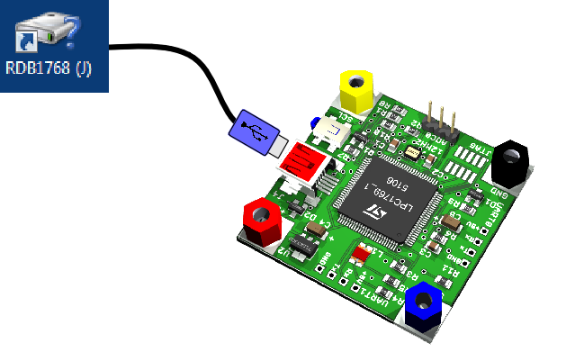
Connect the LPC1769 board to your PC via the USB mini-B connector. Build the bootloader within the IDE and then load it into flash using the in circuit emulator. Once the bootloader has been downloaded, you can then disconnect the in circuit emulator. The LPC1769 will power up and the bootloader will execute:
1) If the LPC1769 reset button is not pressed, the user application starts.
2) If the LPC1769 reset button is pressed and held for 2 seconds, the bootloader starts.
Uploading a binary
Once the bootloader enters USB mass storage mode, the connected PC should detect the board as a USB removable drive. With Windows you will see a single file called “firmware.bin” which fills the whole of the flash drive.
To upload a new user application
1) Delete “firmware.bin”
2) Upload a single binary image
3) Dismount the drive from within Windows
4) Reset the board to execute the uploaded binary.
The USB mass storage interface for the bootloader is not intended to provide a generic flash drive. Copying multiple files to the device flash, and then deleting some of them, may not give the behaviour that you expect. Note also that the bootloader will not preserve file information between resets. The next time the board boots in USB mode, you will always see just a single file ‘firmware.bin’.
Creating applications to upload via the bootloader
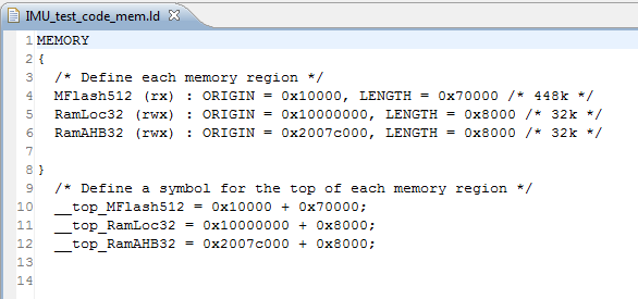
The bootloader uses the top 448KB of the LPC1769’s 512KB of flash as a memory drive.
Applications that you upload via the bootloader need to be built slightly differently, as they will start execution at address 0x10000 rather than 0x00000. This is done by modifying the scripts used by the linker to control code and data placement.
Modifying your linker scripts
When creating applications to be uploaded with the bootloader, you need to bypass the default managed linker script mechanism and create your own linker scripts. The following steps create suitable linker scripts.
1) Create a new subdirectory within your project called, say, “linkscripts”.
2) Build the application for debug. This will create the three managed link script (.ld) files in the Debug subdirectory of your project.
3) Copy the three managed linker script (.ld) files into the linkscripts directory.
4) Modify the filenames of the linker script files in your linkscripts directory to remove the word “Debug”. Thus ” IMU_test_code _Debug.ld” would become ” IMU_test_code.ld”, and similarly for the other two .ld files.
5) Open the file ” IMU_test_code.ld”. Near the top of this file you will see two INCLUDE statements. Modify these to remove the word “Debug” and to insert path information. Thus they will become:
INCLUDE “IMU_test_code_lib.ld”
INCLUDE “IMU_test_code_mem.ld”
6) Now open the file ” IMU_test_code _mem.ld”. You need to change two lines in this file, such that the base address used for the image is 64KB (0x10000) rather than 0x000000, and the length of the flash is 448KB (0x70000) rather than 512KB (0x80000).
Having created your own linker script files, you now need to turn off the managed linker script mechanism. To do this:
1) Open the Project properties.
2) In the left-hand list of the Properties window, open “C/C++ Build” and select “Settings” and then the “Tool Settings” tab.
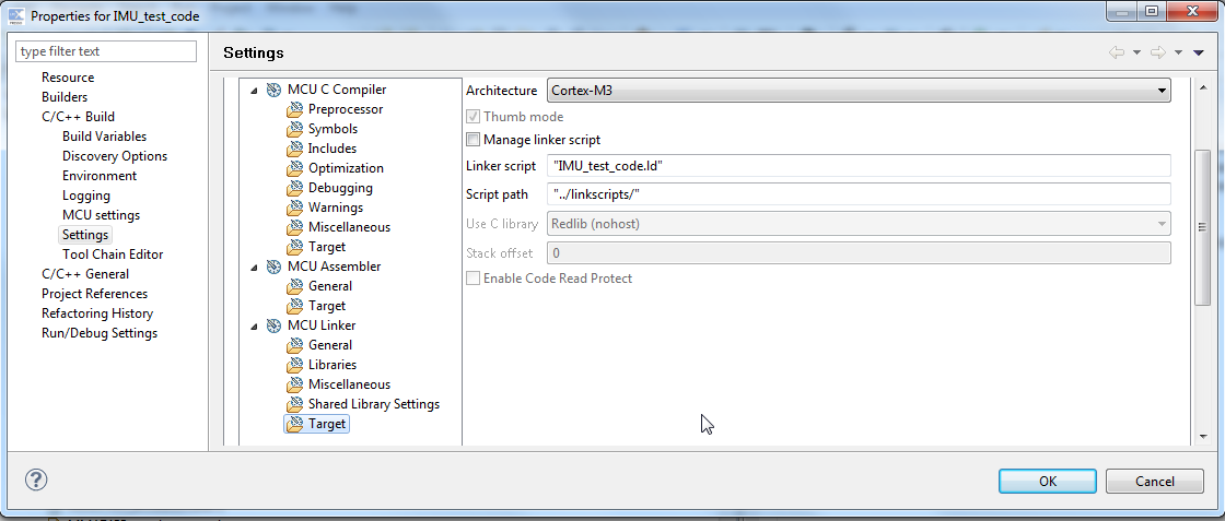
3) Now choose “MCU Linker – Target” and untick the Manage linker script box.
4a) Now enter the name of the your linker script into the Linker script field ie) ” IMU_test_code.ld ”
4b) Now enter the relative path information into the Script path field ie) ” ../linkscripts/ ”
5) Repeat the previous steps for the Release build .
Creating a binary image
By default, the Code Red tools suite creates an ELF image (Executable Linkable Format) which is suitable for downloading via the debugger. However to use the bootloader, you need to convert this into a plain binary file suitable for the processor to execute directly from memory.
To do this automatically each time you carry out a build, you can modify you projects post-build steps as follows:
1) Open the Project properties.
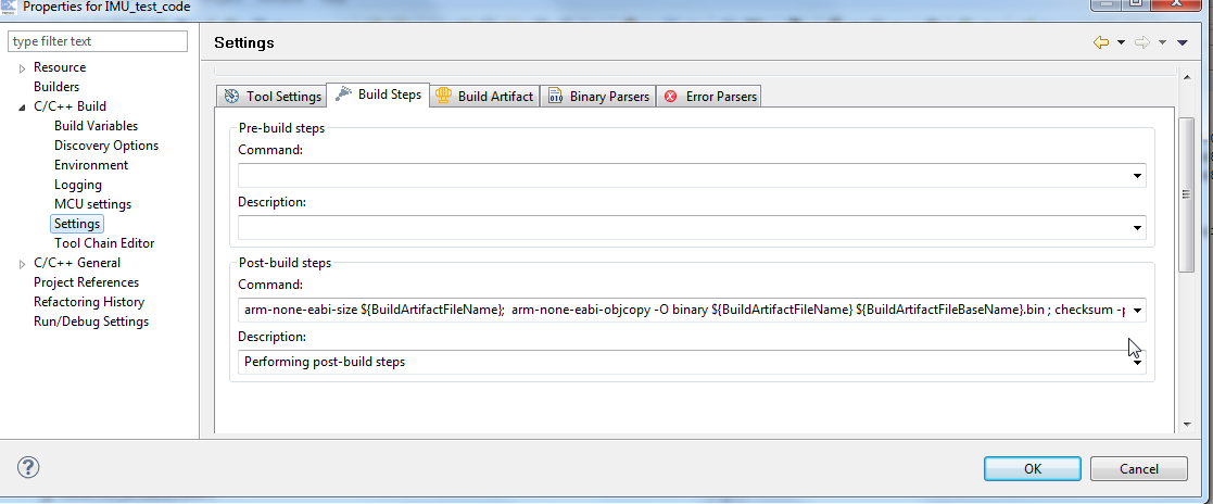
2) Select “C/C++ Build” -> “Settings” and switch to the “Build Steps” tab.
3) In the “Post-build steps” box, you need to add the following command:
arm-none-eabi-size ${BuildArtifactFileName}; arm-none-eabi-objcopy -O binary ${BuildArtifactFileName} ${BuildArtifactFileBaseName}.bin ; checksum -p ${TargetChip} -d ${BuildArtifactFileBaseName}.bin; arm-none-eabi-objcopy -I binary ${BuildArtifactFileBaseName}.bin -O ihex ${BuildArtifactFileBaseName}.hex
4) Repeat the previous steps for the Release build .


1 comment for “LPC1769 Bootloader”